
In mechanical operation, pneumatic actuators play a vital role, which requires everyone to understand the installation, commissioning, maintenance and failure analysis of pneumatic actuators. Only the correct installation operation and necessary maintenance can be used. The valve repair work has achieved the due effect and application purpose.
installment and debugging
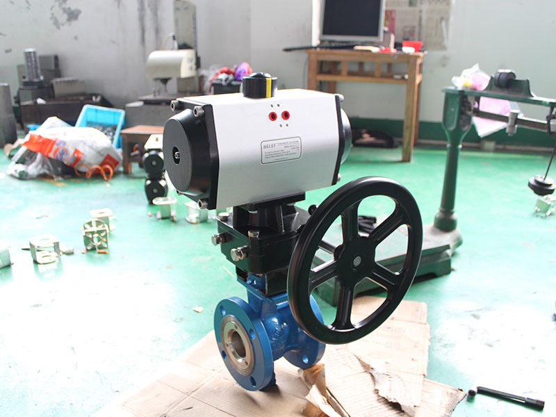
1. Installation of actuator and valve
1. After getting the cylinder, first check whether the model of the cylinder is correct, and check that the cylinder is in the open and closed state. Under normal circumstances, it is closed during installation. (Large diameter valves can also be installed in the open state).
2. Check the direction of rotation of the cylinder, turn the valve counterclockwise to open the valve, and turn the valve clockwise to close the valve.
3. When connecting the cylinder and the valve, check whether the center distance of the cylinder connection hole is consistent with the center distance of the flange connection hole on the valve.
4. Check whether the cylinder axis is consistent with the valve axis. If the axis is inconsistent, please install a square sleeve.
5. The cylinder must be installed in the same state as the valve. (Note that one cannot be in the open state, and the other cannot be in the closed state, otherwise the direction of rotation of the valve will be reversed).
6. Installation situation: (no special requirements) butterfly valve and actuator are installed at 90 degrees. The ball valve is installed in parallel with the actuator.
2. Install solenoid valve (as required)
1. After installing the pneumatic actuator, if you need to install the solenoid valve, please pay attention to whether the O-ring on the solenoid valve is intact.
2. After installation, ventilate and check whether the valve is completely closed, otherwise remove the solenoid valve and reinstall it by rotating it 180 degrees. (No special requirements after installation, fully enclosed).
3. Install answering equipment
1. First remove the screw on the indicator cover at the upper end of the cylinder, insert the connecting shaft of the responder into the groove of the central shaft of the cylinder, and then fix the connecting bolt.
2. Open the upper cover of the responder and check whether the stroke stop corresponds to the valve switch. When the valve is fully open, the yellow square presses the switch, and when the valve is fully closed, the red square presses the switch. When installing the upper cover, the instructions on the upper cover should be consistent with the opening and closing of the valve.
4. Debug
1. If there is no solenoid valve, ventilate from one end first, and check whether the valve opening or closing position is in place. If it is not in place, loosen the corresponding limit screw slightly outward, the number depends on the difference between the valve positions. One is the open limit and the other is the closed limit. Usually the left side of the actuator is the open valve, and the right side is the closing valve. Limit switches are usually left open limit and right close limit. (The counterclockwise rotation stroke increases, and the clockwise rotation stroke decreases). (Note: It should be locked after adjustment)
2. After the solenoid valve is installed, ventilate first to check whether the solenoid valve is completely closed, otherwise, check the solenoid valve and valve installation. Use the manual switch on the solenoid valve to debug and check whether the fully open and fully closed positions of the valve are in place. If you need to adjust the stroke, the method is the same as above.
 customer service1
  customer service2